GPU Slicing in Production AI Systems: Comparing MIG, MPS, Time-Slicing, and Dynamic Partitioning
Modern production AI systems rarely deploy a single standalone large language model. Contemporary compound AI architectures rely on heterogeneous pipelines comprising embedding models (such as BGE or E5), cross-encoder rerankers, safety classifiers (such as Llama Guard), speculative decoding draft models, and vision-language encoders. While primary generation models typically require dedicated multi-GPU configurations, these auxiliary models often need only a fraction of an accelerator's compute cores and memory.
Allocating a dedicated 80GB accelerator such as an NVIDIA H100 or A100 to an auxiliary service that requires 4GB of VRAM and consumes 10% of available Streaming Multiprocessors (SMs) results in substantial infrastructure waste. Conversely, naively running multiple unisolated workloads on a single GPU introduces severe memory contention, out-of-memory crashes, and tail latency degradation. Managing multi-tenant GPU workloads requires choosing between hardware-level partitioning, CUDA runtime multiplexing, and temporal scheduling.

The Underutilization Problem in Compound AI Workloads
GPU utilization during inference is governed by two constraints: memory bandwidth and compute saturation. Large autoregressive models during generation are memory-bandwidth-bound, whereas smaller auxiliary models (such as embedding encoders or cross-encoder rerankers processing dense batches) are often compute-bound or memory-capacity-underutilized.
When small models run on modern data center GPUs:
- Memory Allocation Waste: A 500M parameter embedding model requires less than 2GB of VRAM in FP16 precision. Placing this service on an 80GB GPU leaves 97% of available memory idle unless shared.
- Compute Under-Subscription: Small models execute kernels that cannot populate the thousands of CUDA cores and hundreds of SMs on modern silicon, leading to low occupancy.
- Head-of-Line Blocking: Uncontrolled multi-process execution causes GPU context switching overheads, serializing kernel launches and introducing unpredictability in Time-To-First-Token (TTFT) and batch inference latency.
To address these inefficiencies, infrastructure teams utilize three primary GPU sharing techniques: Multi-Instance GPU (MIG), Multi-Process Service (MPS), and Time-Slicing.
NVIDIA Multi-Instance GPU (MIG): Hardware-Level Isolation
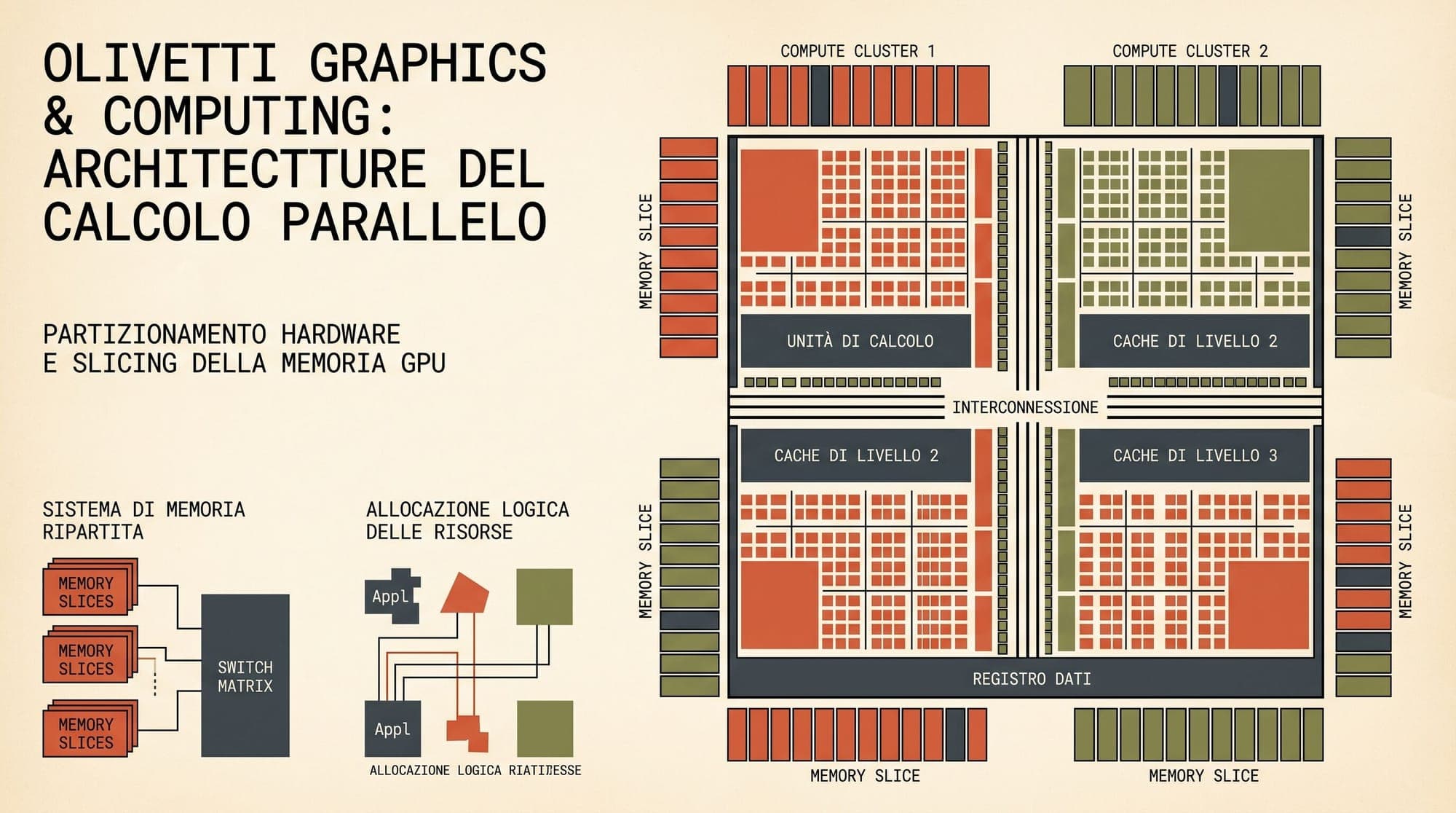
Introduced in the NVIDIA Ampere architecture and extended in Hopper and Blackwell, Multi-Instance GPU (MIG) divides physical silicon into up to seven independent GPU instances.
Unlike software virtualization, MIG partitions physical hardware components:
- Streaming Multiprocessors: Dedicated compute slices (SM clusters).
- Memory Controllers and DRAM Channels: Hardwired memory bus slices and isolated high-bandwidth memory (HBM) capacity.
- Crossbars and L2 Cache: Dedicated portions of the shared L2 cache hierarchy.
- DMA and Copy Engines: Independent PCIe and NVLink bandwidth channels.
Profile Structure and Allocation
MIG instances follow the naming convention {G}g.{M}gb, where G represents the number of compute slices (fractions of SMs) and M represents the allocated memory capacity in gigabytes. On an 80GB H100 or A100, common configurations include:
1g.10gb: 1/7th of total compute, ~10GB VRAM, 1 NVDEC decoder.2g.20gb: 2/7th of compute, ~20GB VRAM, 2 NVDECs.3g.40gb: 3/7th of compute, ~40GB VRAM, 3 NVDECs.4g.40gb: 4/7th of compute, ~40GB VRAM.7g.80gb: Full device operating as a single instance.
Advantages and Operational Constraints
The primary advantage of MIG is strict quality-of-service (QoS) and fault isolation. An out-of-memory exception or fatal CUDA memory fault inside one MIG instance does not affect adjacent instances running on the same physical chip. Compute and memory bandwidth are strictly deterministic.
However, MIG introduces operational trade-offs:
- Static Configuration: MIG profiles must be configured in advance. Dynamically resizing or repartitioning a GPU requires terminating active workloads and reallocating instances.
- No Resource Borrowing: If an instance assigned a
1g.10gbslice is idle, neighboring instances cannot dynamically burst into its compute cores or memory bandwidth. - Hardware Limitations: MIG is restricted to datacenter architectures (A100, H100, H200, B200) and is unavailable on cost-effective inference accelerators like the L4 or L40S.
NVIDIA Multi-Process Service (MPS): Spatial Multiplexing
NVIDIA Multi-Process Service (MPS) is a client-server runtime implementation of the CUDA API designed for concurrent multi-application execution. Rather than carving hardware into rigid physical boundaries, MPS enables multiple CUDA applications to share compute and memory resources concurrently.
Architecture and Execution Model
MPS operates using three distinct components:
- Control Daemon: Spawns and monitors the MPS server process.
- MPS Server: Acts as an intermediary, multiplexing client kernel requests through a single shared CUDA context.
- MPS Clients: Application processes (e.g., PyTorch, ONNX Runtime, or Triton inference containers) connecting via IPC.
Without MPS, when multiple processes submit work to a single GPU, the hardware driver time-slices kernel execution sequentially, forcing costly CUDA context swaps (which incur register file saves and cache flushes). With MPS, kernels from different processes are scheduled simultaneously across available SMs (spatial multitasking), dramatically improving utilization for small batch sizes.
Resource Controls and Isolation Boundaries
MPS provides software-level resource limits through environment variables and control scripts:
CUDA_MPS_PINNED_DEVICE_MEM_LIMIT: Restricts the maximum VRAM an individual client process can allocate (e.g.,0=8G,1=12G).CUDA_MPS_ACTIVE_THREAD_PERCENTAGE: Restricts the percentage of total SM execution threads an application can consume simultaneously (e.g.,20for 20% compute capacity).
Trade-Offs and Failure Domains
While MPS offers flexible, fine-grained resource slicing and high aggregate throughput, it lacks hardware isolation:
- Shared Fault Domain: Because all MPS clients operate under a unified server context, an unhandled fatal CUDA error, segment violation, or hardware exception in one client process can crash the entire MPS server, terminating every co-located service.
- Cache Contention: Co-located processes compete for the same shared L2 cache and memory bus, which can introduce latency variance during bursty traffic.
Temporal Multiplexing: Kubernetes GPU Time-Slicing
GPU Time-Slicing is a software mechanism implemented at the container runtime and orchestrator level via the NVIDIA Kubernetes Device Plugin.
Time-slicing does not partition physical hardware or run kernels concurrently. Instead, it exposes a single physical GPU as multiple logical devices (e.g., configuring replicas: 4 causes a single GPU to advertise as four available nvidia.com/gpu resources in Kubernetes).
Scheduling Dynamics
When multiple containers are scheduled onto logical replicas:
- The NVIDIA container runtime assigns all containers to the same physical device ID.
- The GPU hardware scheduler executes kernels round-robin across processes.
- Each process gains access to the entire GPU's compute and memory during its active time slice.
Operational Trade-Offs
Time-slicing is universally compatible across all NVIDIA architectures (including entry-level GPUs such as T4, L4, and consumer RTX cards) and requires no static hardware configuration.
However, time-slicing is unsuitable for latency-sensitive multi-tenant production inference:
- Zero Memory Isolation: Any container can allocate the full device VRAM. If container A expands its KV cache, container B will encounter an immediate out-of-memory error.
- Severe P99 Latency Penalty: When multiple services experience simultaneous request spikes, time-slicing serializes kernel execution, creating substantial latency queuing.
Architectural Comparison and Trade-Off Dimensions
Choosing the correct GPU slicing model requires balancing isolation, hardware flexibility, and workload predictability across key dimensions:
1. Isolation Mechanism and Execution Mode
- NVIDIA MIG: Provides hardware-level isolation across SMs, high-bandwidth memory controllers, and L2 cache crossbars. Compute instances execute concurrently on dedicated physical hardware slices.
- NVIDIA MPS: Provides software runtime isolation through a CUDA IPC server daemon. Enables concurrent spatial execution across shared SMs without context switching overhead.
- GPU Time-Slicing: Provides driver-level temporal multiplexing. Executes workloads sequentially in round-robin time slices on the full GPU, forcing serialized execution.
2. Fault Containment and Memory Safety
- NVIDIA MIG: Complete fault containment. An out-of-memory error or memory access violation in one instance is strictly isolated and cannot impact adjacent instances.
- NVIDIA MPS: Shared failure domain. Because client processes share the MPS server context, an unhandled fatal CUDA exception or driver crash terminates all co-located services. Memory boundaries are enforced via software limits.
- GPU Time-Slicing: Partial process-level isolation, but zero memory boundaries. Any container can allocate the full device VRAM, creating high risk of cascade OOM failures.
3. Latency Predictability and Hardware Compatibility
- NVIDIA MIG: High latency predictability with guaranteed quality-of-service and dedicated memory bandwidth. Restricted to datacenter GPUs (A100, H100, H200, B200). Reconfiguration requires pod eviction.
- NVIDIA MPS: Medium latency predictability due to potential L2 cache and memory bus contention under bursty load. Compatible with Kepler and newer architectures. Reconfiguration overhead is low.
- GPU Time-Slicing: Low latency predictability due to request queuing under concurrent load. Compatible with all NVIDIA CUDA-capable GPUs. Configuration updates require minimal overhead.
Production Deployment Patterns in Kubernetes
Deploying fractional GPU architectures at scale requires coordinating the NVIDIA GPU Operator, Kubernetes Dynamic Resource Allocation (DRA), and inference runtime proxies.
1. The Isolated Auxiliary Tier Pattern
In production compound AI systems, dedicating full H100 SXM5 accelerators to embedding or guardrail pipelines is economically inefficient. Instead, infrastructure architects deploy heterogeneous GPU pools:
- Tier 1 (Frontier Generation): Dedicated unpartitioned H100/H200 nodes running high-throughput serving runtimes (such as vLLM or SGLang) with continuous batching and PagedAttention.
- Tier 2 (Heavy Auxiliary & Draft Models): H100 nodes partitioned via MIG into
2g.20gband3g.40gbslices to run speculative decoding draft models, multi-modal vision encoders (ColPali/SigLIP), and heavy document parsers. - Tier 3 (Lightweight Auxiliary Services): L4 or A10G nodes running NVIDIA MPS with defined thread percentages to co-locate embedding endpoints, cross-encoder rerankers, and input/output guardrail classifiers.
2. Configuring NVIDIA MPS via Kubernetes Device Plugin
To deploy cooperative MPS sharing securely in Kubernetes, the device plugin ConfigMap is configured to expose MPS resources, while container specs enforce memory caps:
apiVersion: v1
kind: ConfigMap
metadata:
  name: nvidia-device-plugin-mps-config
  namespace: gpu-operator
data:
  config.yaml: |
    version: v1
    flags:
      migStrategy: "none"
    sharing:
      mps:
        resources:
          - name: nvidia.com/gpu
            replicas: 4
In the corresponding inference deployment, memory boundaries are enforced using the MPS device limits:
apiVersion: apps/v1
kind: Deployment
metadata:
  name: embedding-service
spec:
  replicas: 4
  template:
    spec:
      containers:
      - name: embedding-container
        image: vllm/vllm-openai:latest
        env:
        - name: CUDA_MPS_PINNED_DEVICE_MEM_LIMIT
          value: "0=6144M"
        - name: CUDA_MPS_ACTIVE_THREAD_PERCENTAGE
          value: "25"
        resources:
          limits:
            nvidia.com/gpu: 1
3. Dynamic Resource Allocation (DRA) and Container Device Interface (CDI)
Modern Kubernetes environments (Kubernetes 1.30+) leverage Dynamic Resource Allocation (DRA) and the Container Device Interface (CDI) to replace static device plugin mechanisms.
DRA allows workloads to request GPU resources using structured resource claims with fine-grained attributes, such as requesting a specific MIG profile or declaring an MPS compute fraction. This decouples the cluster scheduling layer from static node-level configuration, allowing automated orchestrators to assign workloads to appropriate silicon slices dynamically.
Engineering Summary
Achieving cost-efficient AI infrastructure requires matching the isolation properties of the GPU partitioning mechanism to the trust and latency requirements of each workload:
- Use NVIDIA MIG when running multi-tenant infrastructure, distinct organizational workloads, or services with strict, contractual latency SLAs requiring guaranteed memory bandwidth and crash isolation.
- Use NVIDIA MPS when consolidating multiple trusted internal services (such as co-located embedding and reranking microservices) where high throughput and full SM utilization outweigh the risk of shared failure domains.
- Use Time-Slicing exclusively for development, testing, and batch processing where bursty latency spikes and occasional memory contention are acceptable.
Sources
- NVIDIA Multi-Instance GPU (MIG) User Guide
- NVIDIA Multi-Process Service (MPS) Architecture Overview
- NVIDIA GPU Operator: GPU Sharing and Time-Slicing Documentation
- Kubernetes Documentation: Dynamic Resource Allocation (DRA)
- NVIDIA Technical Blog: Maximize AI Infrastructure Throughput by Consolidating Underutilized GPU Workloads